Distribution by
Mouser
Mouser
Assembly settings
Front
Front form
Round
Round
choose ...
Front bezel colour
Black
Black
choose ...
Front bezel material
Plastic
Plastic
choose ...
Front dimension
Ø 19 mm
Ø 19 mm
choose ...
Mounting
Design
Flush
Flush
choose ...
Mounting type
Panel mounting
Panel mounting
choose ...
Operating-/Indication part
Lens illumination
Illuminated
Illuminated
choose ...
Electrical characteristics
Contacts
1 NC
1 NC
choose ...
Switching rating
42 V @ 0,1 A
42 V @ 0,1 A
choose ...
Mechanical Characteristics
Terminal
Soldering terminal
Soldering terminal
choose ...
Switching system
Snap-action switching element
Snap-action switching element
choose ...
Contact material
Gold
Gold
choose ...
Switching action
Maintained
Maintained
choose ...
Ambient Condition
IP front protection
IP40, according to IEC 60529
IP40, according to IEC 60529
choose ...
Other
Internal size
Ø 13,8 mm
Ø 13,8 mm
choose ...
Back

Your product:

Product range
- Product Status:
- Phase-out
Front
- Front dimension:
- Ø 19 mm
- Front form:
- Round
- Front bezel colour:
- Black
- Front bezel material:
- Plastic
Mounting
- Design:
- Flush
- Mounting type:
- Panel mounting
Operating-/Indication part
- Lens illumination:
- Illuminated
Electrical characteristics
- Switching voltage and switching current:
- 100 mA at 42 VAC/VDC
- Contacts:
- 1 NC
- Switching rating:
- 42 V @ 0,1 A
- Electrical lifetime:
- ≥500 000 cycles of operation at 30 VDC, 100 mA, according to IEC 61058-1
- Electric strength:
- 500 VAC, 50 Hz, 1 minute, as per IEC 60512-2-11 between all terminals and earth
Mechanical Characteristics
- Terminal:
- Soldering terminal
- Contact material:
- Gold
- Switching action:
- Maintained
- Switching system:
- Snap-action switching element
- Switching system:
- The snap-action switching system was designed for switching low powers in electronic circuits. Single-break snap-action contact.
- Mechanical lifetime:
- 1 Mil. cycles of operation (RCC/RPB)
- Operating force:
- 1.4 N
- Operating Travel:
- ca. 2.2 mm ± 0.2 mm
- Tightening torque:
- Fixing nut max. 0.2 Nm
- Wire cross section:
- Max. wire cross-section 2 wires with 0.5 mmMax. wire cross-section of stranded cable 1 x 0.75 mm²Wire cross-section of terminal 1,6 x 0,4 mm²
- Weight:
- 0.034 kg
Ambient Condition
- IP front protection:
- IP40, according to IEC 60529
- Operating temperature:
- – 25 °C … + 65 °C
- Storage temperature:
- – 40 °C … + 80 °C
- Shock resistance:
- 50 g for 11 ms, as per DIN / EN 60068-2-27 (Single impacts, semi-sinusoidal)
- Vibration resistance:
- 10 g at 10 Hz…2000 Hz, amplitude 0.75 mm (Sinusoidal), according to DIN EN 60512-4-4
Certificate
- Conformities:
- 2011 / 65 / EC (RoHS), 2014 / 35 / EU (LVD) for version 230 VAC
- REACH:
- REACH compliant
- RoHS:
- RoHS compliant
Other
- Short Description:
- Actuator, Ø 19 mm, Illuminated, Round, Black, Plastic, 1 NC, Maintained, Soldering terminal, IP40, according to IEC 60529
- Internal size:
- Ø 13,8 mm
- Housing colour:
- Black
- Housing material:
- Plastic
- Product attributes:
- +/- terminals are not connected
- Wiring diagrams:
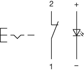
- Component layouts:
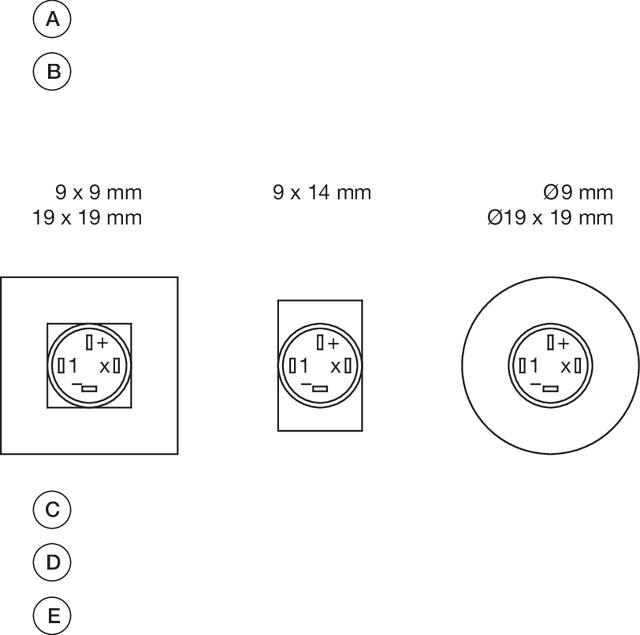 A = Terminals (rear side)
B = Illuminated pushbutton
C = x = Contact No.
D = 2 = Normally open
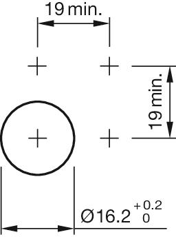
E = 4 = Normally close- Mounting cut-outs:
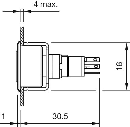
- Dimension drawings:
Download files
Not available