Distributie via
Mouser
Mouser
Assembly settings
Voor
Front form
Round
Round
kiezen...
Front bezel colour
Nature
Nature
kiezen...
Front bezel material
Aluminium
Aluminium
kiezen...
Front dimension
Ø 25 mm
Ø 25 mm
kiezen...
Montage
Design
Flush
Flush
kiezen...
Mounting type
Panel mounting
Panel mounting
kiezen...
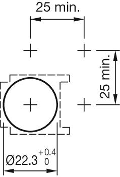
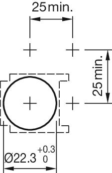
Mounting cut-out
Ø 22 mm
Ø 22 mm
kiezen...
Bedienings-/display-eenheid
Lens shape
Flush
Flush
kiezen...
Lens colour
Colourless
Colourless
kiezen...
Lens material
Plastic, according to UL 94 HB
Plastic, according to UL 94 HB
kiezen...
Lens illumination
Illuminated
Illuminated
kiezen...
Shape of illumination
Front
Front
kiezen...
Illumination colour
Blue
Blue
kiezen...
Elektrische kenmerken
Operating voltage kind of
V AC/DC
V AC/DC
kiezen...
Operating voltage
24 V
24 V
kiezen...
Mechanische kenmerken
Terminal
PCB terminal
PCB terminal
kiezen...
Omgevingscondities
IP front protection
IP65
IP65
kiezen...
Meer
Material
Plastic
Plastic
kiezen...
Terug
Distributie via
Mouser
Mouser
Indicator, Series 71, Ø 25 mm, Flush, IP65, PCB terminal
- 61-9642.7
- 71-600.0
- 61-9933.0
- 71-670.006
- 10-2J12.1066
- Lens colour
- Lens material
- Front form
- Shape of illumination


- Front dimension
- Front bezel colour
- Front bezel material
- Mounting cut-out


- Operating voltage kind of
- Illumination colour
- Operating voltage

Accessoires & gereedschap toevoegen
Uw product:
Assortiment
- HMI function:
- Indicator
- Series:
- Series 71
Voor
- Front dimension:
- Ø 25 mm
- Front form:
- Round
- Front bezel colour:
- Nature
- Front bezel material:
- Aluminium
Montage
- Design:
- Flush
- Mounting cut-out:
- Ø 22.5 mm
- Mounting type:
- Panel mounting
Bedienings-/display-eenheid
- Lens colour:
- Colourless
- Lens material:
- Plastic, according to UL 94 HB
- Lens illumination:
- Illuminated
- Lens shape:
- Flush
- Lens optics:
- transparent
- Illumination colour:
- Blue
- Shape of illumination:
- Front
Elektrische kenmerken
- Operating voltage:
- 24 V AC/DC +10%
- Operation current:
- 7 - 14 mA ±15 %
- Lumi. Intensity:
- 650 mcd
Mechanische kenmerken
- Terminal:
- PCB terminal
- Totaal gewicht:
- 0.016 kg
Omgevingscondities
- IP front protection:
- IP65
- Operating temperature:
- – 25 °C … + 55 °C
Meer
- Material:
- Plastic
- Housing material:
- Plastic
- Product attributes:
- For indicator, push button, illuminated push button
- Wiring diagrams:

Product opslaan of delen
Bestanden downloaden
Niet beschikbaar.
Uw product bestaat uit het volgende 5 COMPONENTS:

Voor
- Front form:
- Round
Bedienings-/display-eenheid
- Lens colour:
- Colourless
- Lens material:
- Plastic, according to UL 94 HB
- Lens illumination:
- Illuminated
- Lens shape:
- Flush
- Lens optics:
- transparent
- Shape of illumination:
- Front
Mechanische kenmerken
- Weight:
- 0.001 kg
Certificaten
- REACH:
- REACH compliant
- RoHS:
- RoHS compliant
Meer
- Short Description:
- Lens, Ø 19.7 mm, Illuminated, Colourless, Flush, Plastic, according to UL 94 HB
- Dimension:
- Ø 19.7 mm
Bestanden downloaden
Niet beschikbaar.

Montage
- Mounting type:
- Panel mounting
Mechanische kenmerken
- Weight:
- 0.004 kg
Omgevingscondities
- IP Protection:
- IP65 front side
- Operating temperature:
- – 25 °C … + 55 °C
Certificaten
- REACH:
- REACH compliant
- RoHS:
- RoHS compliant
Meer
- Short Description:
- Actuator
- Material:
- Plastic
- Hints:
- Pitch of the front plate mounting holes must agree with the printed circuit board holes Ø 3.5 mm
- Wiring diagrams:
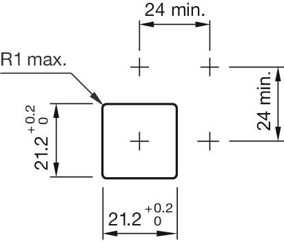
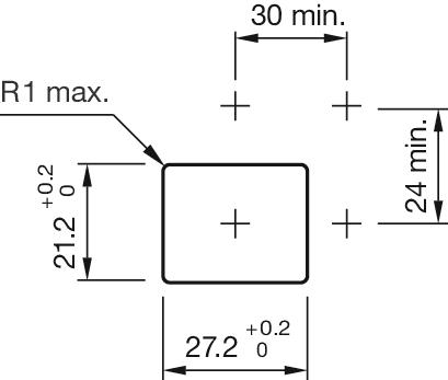
- Mounting cut-outs:
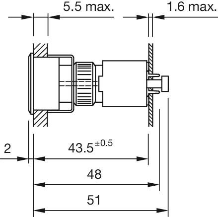
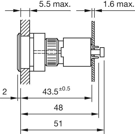
- Dimension drawings:
Bestanden downloaden
Component voor 7.85 USD
Toevoegen aan winkelwagentje

Voor
- Front dimension:
- Ø 25 mm
- Front form:
- Round
- Front bezel colour:
- Nature
- Front bezel material:
- Aluminium
Montage
- Mounting cut-out:
- Ø 22.5 mm
- Mounting type:
- Panel mounting
Mechanische kenmerken
- Weight:
- 0.005 kg
Certificaten
- REACH:
- REACH compliant
- RoHS:
- RoHS compliant
Meer
- Short Description:
- Front bezel set, Ø 25 mm, Ø 19,7 mm, Nature, Aluminium
- Dimension:
- Ø 25 mm
- Internal size:
- Ø 19,7 mm
- Product attributes:
- For indicator, push button, illuminated push button
- Hints:
- The colour of anodised aluminium parts can vary due to technical production reasons
- Mounting cut-outs:
Bestanden downloaden
Component voor 12.65 USD
Toevoegen aan winkelwagentje

Mechanische kenmerken
- Terminal:
- PCB terminal
- Weight:
- 0.005 kg
Certificaten
- REACH:
- REACH compliant
- RoHS:
- RoHS compliant
Meer
- Short Description:
- Lamp element, PCB terminal, Plastic
- Material:
- Plastic
- Housing material:
- Plastic
- Hints:
- Including locking pin
- Wiring diagrams:
- Component layouts:
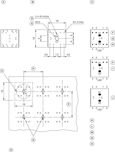 A = Terminals (rear side)
B = Drilling plan (component side)
C = non-metallic
D = Cu-Pad
E = Occupancy plan (component side)
F = 1. Switch
G = Switching element 2 Normaly close + 2 Normaly open, Part No. 71-672.026
H = 2. Switches
I = Switching element 1 Normaly close + 1 Normaly open, Part No. 71-671.026
J = Illumination element, Part No. 71-670.026
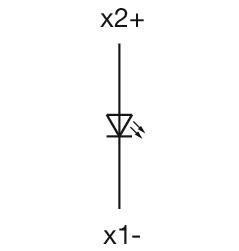
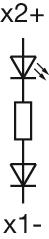
K = X1 Lamp cathode (-)
L = X2 Lamp anode (+)
M = 1-2 Contact normally closed
N = 3-4 Contact normally open
O = 5 Hole for interlocking pin
P = Front dimension min.
Q = Position interlocking pin
R = Note:
Pitch of the print circuit board hole Ø3.5 must agree with the mounting holes on the front plate
S = Slot in actuator
Bestanden downloaden
Component voor 10.20 USD
Toevoegen aan winkelwagentje

Bedienings-/display-eenheid
- Illumination colour:
- Blue
Elektrische kenmerken
- Operating voltage:
- 24 V AC/DC +10%
- Operation current:
- 7 - 14 mA ±15 %
- Lumi. Intensity:
- 650 mcd
Mechanische kenmerken
- Weight:
- 0.001 kg
Certificaten
- REACH:
- REACH compliant
- RoHS:
- RoHS compliant
Meer
- Short Description:
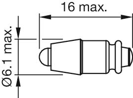
- Single-LED, T1 ¾ MG, Blue, 24 V AC/DC +10%
- Kind of iIllumination:
- Single-LED
- Hints:
- Due to high surface temperatures, the series resistor must not be soldered directly to the terminals of the equipment (use a terminal plate)When using AC/DC types with AC operation, slight flickering can occurThe luminous intensity stated is for when used with DCElectrical and optical data are measured at 25 °CThe specified versions are built with a protection diode (halve wave rectifier) in series and the LEDLuminosity and wave length variations caused by LED manufacturing processes may cause slight differences regarding the illumination. The customer has to decide what resistor shall be used to the LEDWhere supply voltages are over 48 V, a voltage-reduction element (external protective series resistor) must be used.Keep to the country specific safety instructions
- Wiring diagrams:
- Dimension drawings:
Bestanden downloaden
Component voor 16.15 USD
Toevoegen aan winkelwagentje