Mouser
Square
Black
Plastic, according to UL 94 V0
24 mm x 24 mm
Flush
Panel mounting
21 mm x 21 mm
Flush
Colourless
Plastic, according to UL 94 V0
Illuminated
Red
2 NC + 2 NO
250 V @ 3 A
V AC/DC
12 V
Soldering terminal
Snap-action switching element
Gold
Maintained
IP65
Mouser
Illuminated push button, Series 51, 24 mm x 24 mm, illuminative, Flush, 2 NC + 2 NO, Gold, IP65, Soldering terminal
- 61-9671.7
- 51-282.0252F
- 61-9930.0
- 10-2J09.1062
- Front form
- Lens illumination
- Lens colour

- Switching rating
- Switching system
- Switching action
- Lens illumination
- Terminal
- Contacts configuration

- Front dimension
- Front form
- Front bezel colour
- Mounting cut-out

- Operating voltage kind of
- Illumination colour
- Operating voltage

- HMI function:
- Illuminated push button
- Series:
- Series 51
- Front dimension:
- 24 mm x 24 mm
- Front form:
- Square
- Front bezel colour:
- Black
- Front bezel material:
- Plastic, according to UL 94 V0
- Design:
- Flush
- Mounting cut-out:
- 21 mm x 21 mm
- Mounting type:
- Panel mounting
- Lens colour:
- Colourless
- Lens material:
- Plastic, according to UL 94 V0
- Lens illumination:
- Illuminated
- Lens shape:
- Flush
- Lens optics:
- transparent
- Illumination colour:
- Red
- Switching voltage and switching current:
250 VAC, 5 A (ohmic)
250 VAC, 3 A (Soldering terminal)
250 VAC, 2 A (inductive, cos(phi) = 0.7)
125 VAC, 3 A (inductive, cos(phi) = 0.7)
220 VDC, 0.1 A (inductive, L:R = 30 ms)
110 VDC, 0.2 A (inductive, L:R = 30 ms)
60 VDC, 0.7 A (inductive, L:R = 30 ms)
24 VDC, 2 A (inductive, L:R = 30 ms)
- Contacts configuration:
- 2 NC + 2 NO
- Operating voltage:
- 12 V AC/DC +10%
- Operation current:
- 7 - 14 mA ±15 %
- Switching rating:
- 250 V @ 3 A
- Electrical lifetime:
- 50 000 cycles of operation
- Lumi. Intensity:
- 330 mcd
- Thermal current Ith:
- The maximum current in continuous operation and at ambient temperature not exceeding the quoted maximum values.3 A
- Terminal:
- Soldering terminal
- Contact material:
- Gold
- Switching action:
- Maintained
- Switching system:
- Snap-action switching element
- Tightening torque:
- Fixing nut max. 0.5 Nm
- Total weight:
- 0.012 kg
- IP front protection:
- IP65
- Operating temperature:
- – 25 °C … + 55 °C, mounted as a block, make sure the heat can escape freely
- Vibration resistance:
- 10 g at 10 Hz…1500 Hz, amplitude 0.75 mm (Sinusoidal), according to DIN EN 60512-4-4, DIN EN 60068-2-6
- Housing colour:
- Black
- Product attributes:
- For indicator illuminated pushbutton and keylock switch
- max. number of switching elements:
- 4
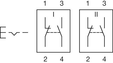
- Wiring diagrams:


- Front form:
- Square
- Lens colour:
- Colourless
- Lens material:
- Plastic, according to UL 94 V0
- Lens illumination:
- Illuminated
- Lens shape:
- Flush
- Lens optics:
- transparent
- Weight:
- 0.002 kg
- REACH:
- REACH compliant
- RoHS:
- RoHS compliant
- Short Description:
- Lens, 18 mm x 18 mm, Illuminated, Colourless, Flush, Plastic, according to UL 94 V0
- Dimension:
- 18 mm x 18 mm

- Design:
- Flush
- Mounting type:
- Panel mounting
- Lens illumination:
- Illuminated
- Switching voltage and switching current:
250 VAC, 5 A (ohmic)
250 VAC, 3 A (Soldering terminal)
250 VAC, 2 A (inductive, cos(phi) = 0.7)
125 VAC, 3 A (inductive, cos(phi) = 0.7)
220 VDC, 0.1 A (inductive, L:R = 30 ms)
110 VDC, 0.2 A (inductive, L:R = 30 ms)
60 VDC, 0.7 A (inductive, L:R = 30 ms)
24 VDC, 2 A (inductive, L:R = 30 ms)
- Contacts:
- 2 NC / 2 NO
- Rated Operational Voltage Ue:
- 250 VAC/DC according to EN IEC 60947-1
- Switching rating:
- 250 V @ 3 A
- Electrical lifetime:
- 50 000 cycles of operation
- Electric strength:
- 2500 VAC, 50 Hz, 1 min. between all terminals and earth, according to IEC 61058-1, part 15
- Protection class:
- ll
- Standards:
- According to EN/IEC 61058-1
- Thermal current Ith:
- The maximum current in continuous operation and at ambient temperature not exceeding the quoted maximum values.3 A
- Terminal:
- Soldering terminal
- Contact material:
- Gold
- Switching action:
- Maintained
- Switching system:
- Snap-action switching element
- Switching system:
- Self-cleaning, double-break snap action switching system, 1 normally closed and 1 normally open contact per element.
- Mechanical lifetime:
- 1 Mil. cycles of operation (RCC/RPB)
- Operating force:
- 1,8 … 6 N, depending on the number of switching elements
- Operating Travel:
- 3 mm
- Tightening torque:
- Fixing nut max. 0.5 Nm
- Wire cross section:
- Snap-action switching element with tinned soldering terminals at the sidesMax. wire diameter 2 wires à 1.2 mmMax. wire cross-section of stranded cable 1 x 1 mm²
- Weight:
- 0.007 kg
- IP front protection:
- IP65, according to DIN EN 60529
- Operating temperature:
- – 25 °C … + 55 °C, mounted as a block, make sure the heat can escape freely
- Storage temperature:
- – 40 °C … + 85 °C
- Shock resistance:
- 15 g for 11 ms, as per DIN / EN 60512-4-3, DIN / EN 60068-2-27 (Single impacts, semi-sinusoidal)
- Vibration resistance:
- 10 g at 10 Hz…1500 Hz, amplitude 0.75 mm (Sinusoidal), according to DIN EN 60512-4-4, DIN EN 60068-2-6
- Climate resistance:
- Standard condition, as per DIN EN 60068-2-30Changing condition, as per DIN EN 60068-2-14
- Approbations:
- CB (IEC 61058-1), CQC, CSA, DNV, EAC, ENEC (EN 61058-1), UL, VDE
- Conformities:
- CE, UKCA, 2011 / 65 / EC (RoHS), 2014 / 30 / EU (EMC), 2014 / 35 / EU (LVD)
- REACH:
- REACH compliant
- RoHS:
- RoHS compliant
- Short Description:
- Actuator, Illuminated, 2 NC / 2 NO, Maintained, Soldering terminal, IP65, according to DIN EN 60529
- Housing colour:
- Black
- max. number of switching elements:
- 4
- Wiring diagrams:
- Component layouts:
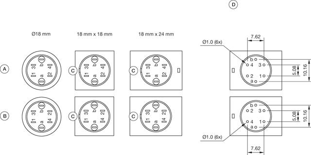 A = Universal terminal (rear side)
B = Plug-in terminal (rear side)
C = Anti twist device
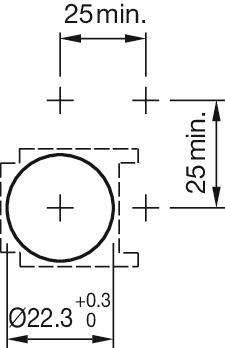
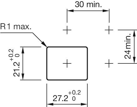
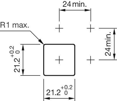
D = Drilling plan- Mounting cut-outs:
- Dimension drawings:
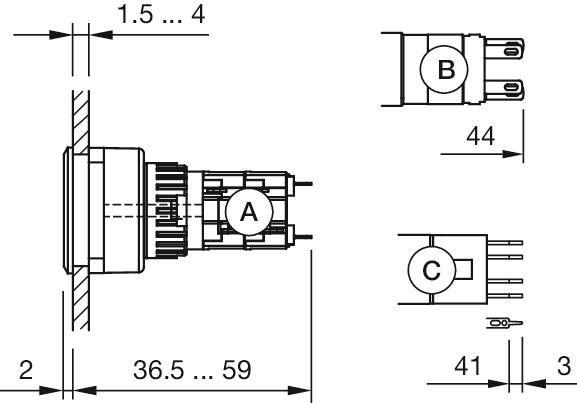 A = Solder terminal
B = Plug-in terminal 2.8 mm x 0.5 mm
C = Universal terminal 2.0 mm x 0.5 mm

- Front dimension:
- 24 mm x 24 mm
- Front form:
- Square
- Front bezel colour:
- Black
- Front bezel material:
- Plastic, according to UL 94 V0
- Mounting cut-out:
- 21 mm x 21 mm
- Mounting type:
- Panel mounting
- Weight:
- 0.003 kg
- REACH:
- REACH compliant
- RoHS:
- RoHS compliant
- Short Description:
- Front bezel set, 24 mm x 24 mm, 18 mm x 18 mm, Black, Plastic, according to UL 94 V0
- Dimension:
- 24 mm x 24 mm
- Internal size:
- 18 mm x 18 mm
- Product attributes:
- For indicator illuminated pushbutton and keylock switch
- Mounting cut-outs:


- Illumination colour:
- Red
- Operating voltage:
- 12 V AC/DC +10%
- Operation current:
- 7 - 14 mA ±15 %
- Lumi. Intensity:
- 330 mcd
- Weight:
- 0.003 kg
- REACH:
- REACH compliant
- RoHS:
- RoHS compliant
- Short Description:
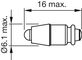
- Single-LED, T1 ¾ MG, Red, 12 V AC/DC +10%
- Kind of iIllumination:
- Single-LED
- Hints:
- Due to high surface temperatures, the series resistor must not be soldered directly to the terminals of the equipment (use a terminal plate)When using AC/DC types with AC operation, slight flickering can occurThe luminous intensity stated is for when used with DCElectrical and optical data are measured at 25 °CThe specified versions are built with a protection diode (halve wave rectifier) in series and the LEDLuminosity and wave length variations caused by LED manufacturing processes may cause slight differences regarding the illumination. The customer has to decide what resistor shall be used to the LEDWhere supply voltages are over 48 V, a voltage-reduction element (external protective series resistor) must be used.Keep to the country specific safety instructions
- Wiring diagrams:
- Dimension drawings: